Integrating a Mitsubishi RJ71EIP91 Ethernet/IP card with an R04 CPU in your iQ-R series PLC system may sound complex, but with the right steps, it’s a smooth process. Whether you’re connecting to third-party Ethernet/IP devices or expanding your Mitsubishi automation network, this guide walks you through the entire setup—from hardware installation to configuration in GX Works3.
1. Hardware Setup – What You’ll Need
Before diving into software, get your physical setup ready:
- Install the RJ71EIP91 module on the iQ-R base unit next to your R04CPU.
- Connect an Ethernet cable to Port 1 of the RJ71EIP91 module (this is the default port for Ethernet/IP communication).
2. Software Requirements
To configure the RJ71EIP91 properly, you’ll need:
- ✅ GX Works3 – Mitsubishi’s standard PLC programming and configuration tool
- ✅ EtherNet/IP Configuration Tool – For loading and managing EDS files
- ✅ The EDS (Electronic Data Sheet) file for any Ethernet/IP slave device you’ll be connecting
3. Configuration Steps in GX Works3
✅ Step 1: Create or Open a Project
- Launch GX Works3.
- Create a new project and select R04CPU as the CPU type.
- Navigate to Module Configuration and add the RJ71EIP91 module in the appropriate slot.
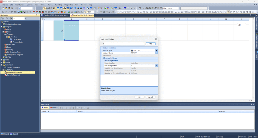
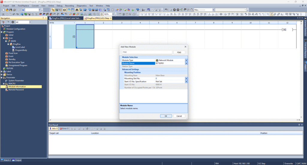
✅ Step 2: Insert the RJ71EIP91 Module
- In the project tree, go to Module Configuration.
- Right-click the slot where the module is installed.
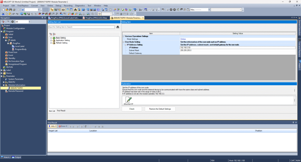
✅ Step 3: Assign Network Settings
- Select the RJ71EIP91 module.
- Configure its IP address and subnet mask (e.g.,
192.168.1.10 / 255.255.255.0) under Ethernet/IP settings.
4. Setting Up Ethernet/IP Devices Using EIP Configurator Tool
Once the card is installed and basic settings are done, now it’s time to set up communication with slave devices.
✅ Step 4: Launch the Ethernet/IP Configurator Tool
- Open the EIP Configurator from GX Works3.
- Click Add and import the EDS file of the device you want to connect (e.g., third-party I/O, VFDs, etc.).
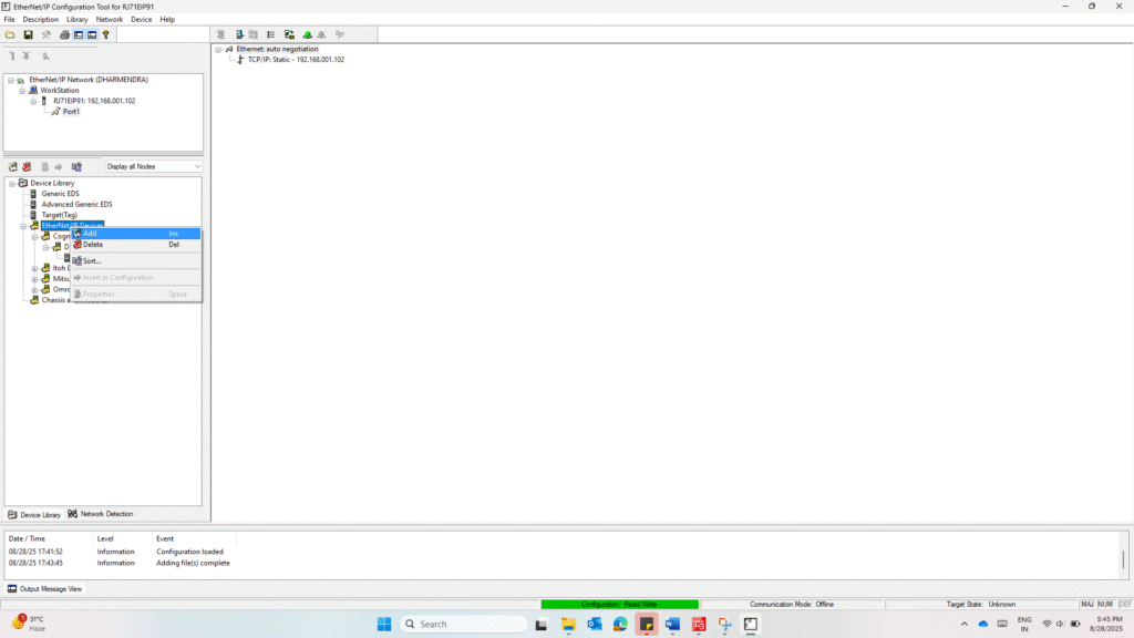
✅ Step 5: Drag the Device from the Library
- Once imported, you’ll see your device listed in the library.
- Drag and drop it into the configuration area.
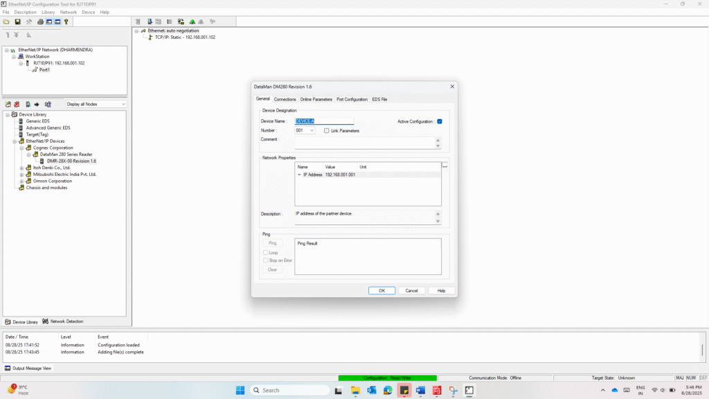
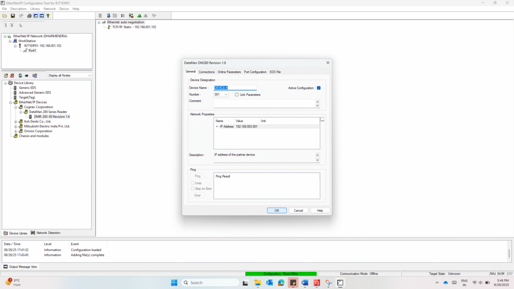
✅ Step 6: Configure Device Settings
- Set the device name and device number.
- Assign the IP address for the slave device.
- Adjust I/O sizes or RPI (Requested Packet Interval) if needed.
✅ Step 7: Download Settings to the Module
- Connect to the RJ71EIP91 via Ethernet.
- Download the configuration to the module.
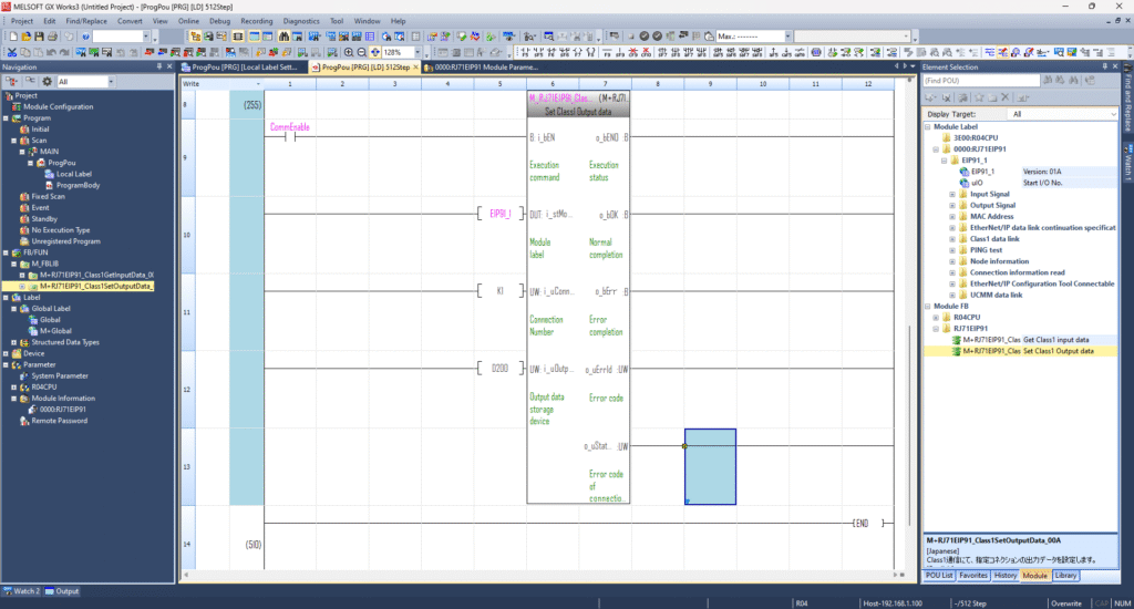
5. Using Function Blocks in Your Ladder Program
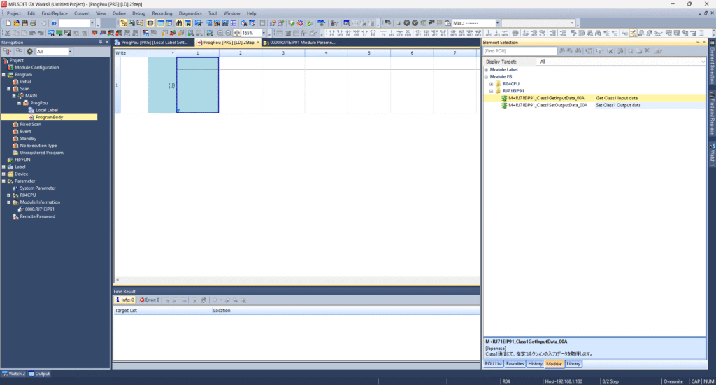
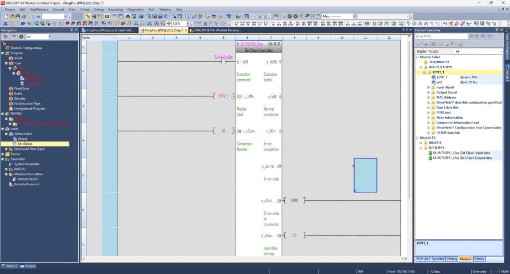
✅ Step 8: Use Built-in Function Blocks
- In GX Works3, go to the Element Selection Window.
- Under Module FBs, drag and drop:
M+RJ71EIP91 Class 1 Get Input DataM+RJ71EIP91 Class 1 Set Output Data
These function blocks allow you to manage I/O communication with your connected Ethernet/IP devices.
Make sure to use the module label names assigned in your project for easy identification.
📚 Mitsubishi Documentation (Highly Recommended)
To explore more advanced features and troubleshoot effectively, Mitsubishi offers official manuals you can reference:
If you’re looking for a hands-on example of Mitsubishi PLC communication, be sure to check out our detailed tutorial here: