Mitsubishi FX5U PID instruction setup explained with full parameter configuration, auto-tuning, ladder logic, and error code guide using GX Works3.
💡 Related: If you’re looking for a quick overview of the FX5U’s built-in PID function, which allows configuration directly through parameters (no programming required), check out our separate post: Built-in PID Function of FX5U – Overview & Setup Guide.
Mitsubishi FX5U PID Instruction Contains
Before diving into ladder logic or programming, let’s break down the key elements of a PID (Proportional‑Integral‑Derivative) control setup:(Download Link For Ladder Logic at the END)
- PV – Process Variable
The input reading (e.g., a sensor’s analog temperature value). - SP – Setpoint
Your desired target value. - MV – Manipulated Variable
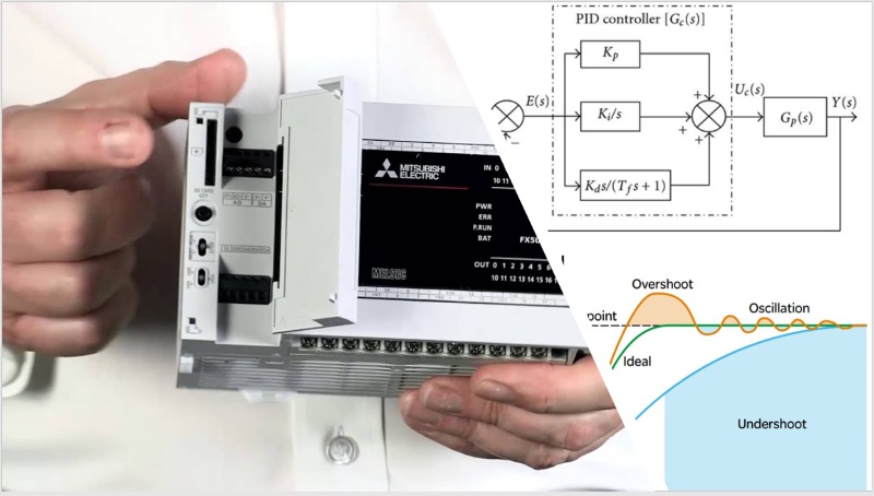
The control output (e.g., analog signal to a heater or valve). - Kₚ (Proportional Gain)
Determines the output’s immediate response to error (SP – PV). - Kᵢ (Integral Gain)
Corrects accumulated past error over time. - K𝒹 (Derivative Gain)
Predicts and dampens future error based on PV’s rate of change. - Sample Time
How often the PID loop recalculates (PLC scan or update interval). - Upper/Lower MV Limits
Prevents overdriving actuators by bounding the output.
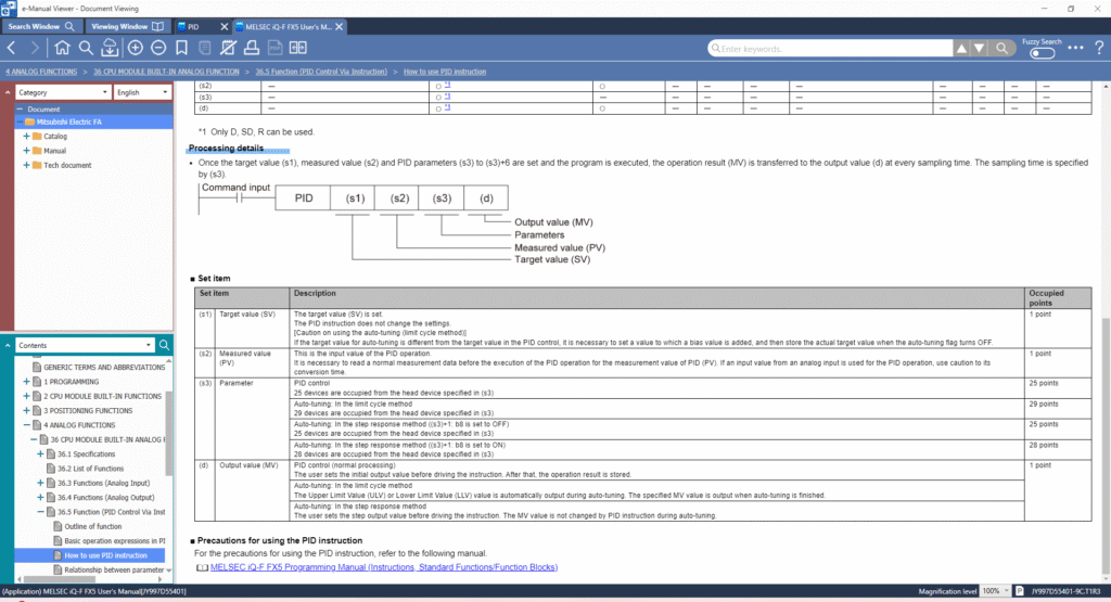
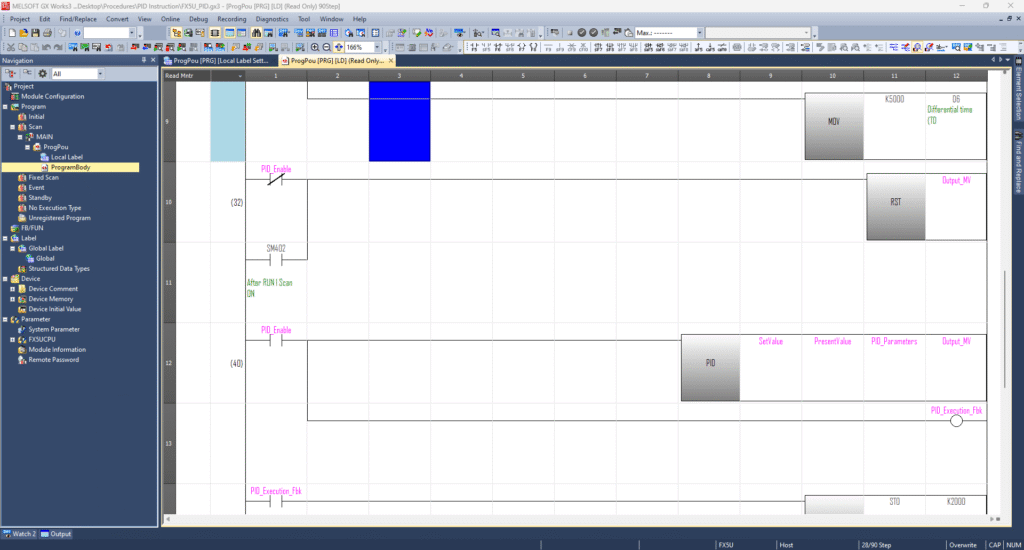
In Mitsubishi’s FX5U series, the PID instruction involves four elements:
- S1 – Set Value (SP)
- S2 – Present Value (PV)
- S3 – Parameter block (up to 29 words)
- D – Output register where MV is stored
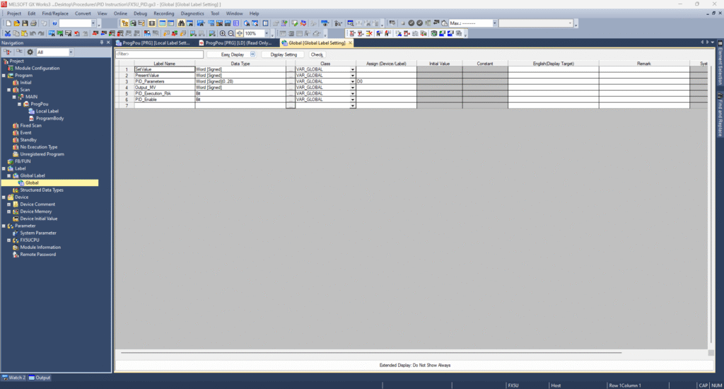
Step‑by‑Step: Setting It Up in GX Works3 for FX5U
- Open GX Works3
- Create a New Project targeting the FX5U CPU
- Go to the Navigation Window → Global Label section
- Define labels such as:
Set_Value(S1)Present_Value(S2)PID_Parameters(S3)Output_MV(D)
- Insert the PID instruction into your ladder or structured program.
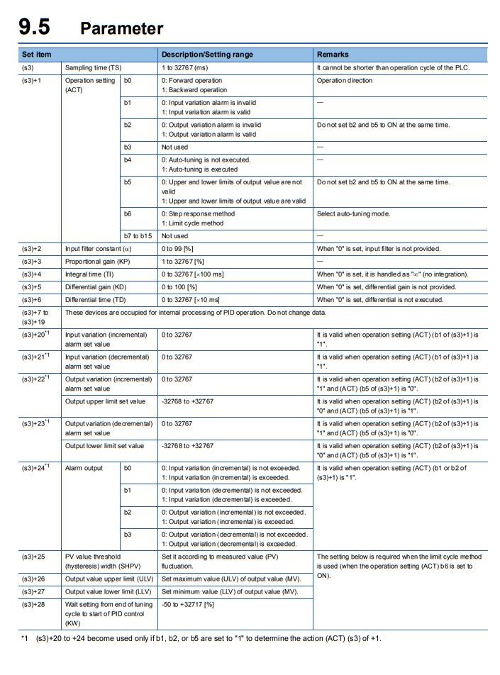
Configuring the PID Parameter Block
Create PID_Parameters as an array of 29 words, starting at, for example, D0 (covers D0–D28). Here’s how to set key elements:
- D0 – Sampling Time: e.g.,
500ms - D1 – Operation Settings (bit flags):
- b0 (D1.0) = 1 → Backward action (heating mode)
- b5 (D1.5) = 1 → Enable upper/lower MV limits
- b7 (D1.7) = 1 → Enable overshoot suppression
- D2 – Input filter constant (if needed)
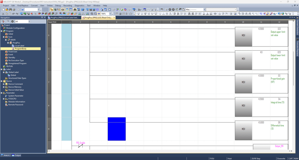
- D3 – Proportional gain (KP): e.g.,
3000 - D4 – Integral time (TI): e.g.,
2000(×100 ms units) - D5 – Differential gain (KD): adjust based on smoothness needs
- D6 – Differential time (TD): e.g.,
5000(×10 ms units)
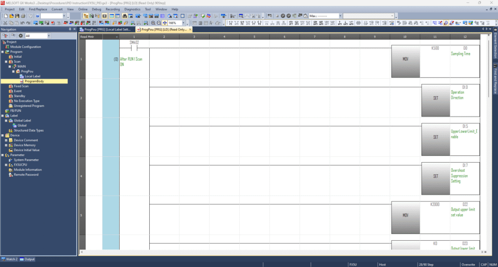
For MV limiting:
- D22 – MV upper limit: e.g.,
2000 - D23 – MV lower limit: e.g.,
0(or another safe min)
You can either manually tune KP, TI, and TD or utilize Mitsubishi’s Auto‑Tuning feature by setting the appropriate bits in D1 and adding required parameters (like hysteresis, wait times, or limits) starting at D25—depending on your tuning strategy.
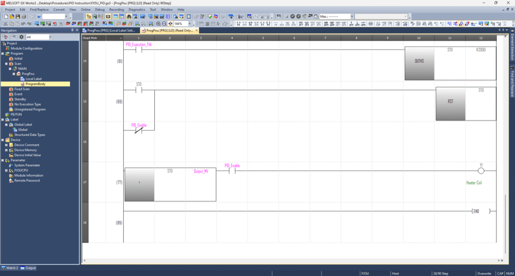
Finally, your MV is output via another designated register, typically labelled Output_MV.
Operation Bit b8 Behavior
| Status | Description |
|---|---|
| ON | Twenty-eight devices are occupied from the device specified in (s3). |
| OFF | Twenty-five devices are occupied from the device specified in (s3). |
Note: (1): Latched data register number is specified to (d).
PID Instruction Error Codes
| Error Code | System Register | Description |
|---|---|---|
| 2820H | SD0 / SD8067 | Invalid connection number in (s1). Must be between 1 and 8. |
| 2822H | SD0 / SD8067 | Device number in (s2), (d), or (n) is out of range. |
| 3500H | SD0 / SD8067 | Sampling time (TS) is less than or equal to 0. |
| 3502H | SD0 / SD8067 | Invalid input filter constant (α < 0 or α ≥ 100). |
| 3503H | SD0 / SD8067 | Invalid proportional gain (KP ≤ 0). |
| 3504H | SD0 / SD8067 | Invalid integral time (TI < 0). |
| 3505H | SD0 / SD8067 | Invalid derivative gain (KD < 0 or KD ≥ 100). |
| 3506H | SD0 / SD8067 | Invalid derivative time (TD < 0). |
| 350AH | SD0 / SD8067 | Sampling time (TS) is less than or equal to the scan time. |
| 350CH | SD0 / SD8067 | Measured value variation exceeds limit (∆PV < -32768 or > 32767). |
| 350DH | SD0 / SD8067 | Deviation exceeds limit (EV out of range). |
| 350EH | SD0 / SD8067 | Integral result exceeds range (-32768 to 32767). |
| 350FH | SD0 / SD8067 | Excessive derivative value due to derivative gain (KD). |
| 3510H | SD0 / SD8067 | Derivative result exceeds range (-32768 to 32767). |
| 3511H | SD0 / SD8067 | PID operation result exceeds allowable range. |
| 3512H | SD0 / SD8067 | Upper MV limit is lower than the lower MV limit. |
| 3513H | SD0 / SD8067 | Invalid alarm setting (set value < 0). |
| 3514H | SD0 / SD8067 | Step response method: Improper auto-tuning result. |
| 3515H | SD0 / SD8067 | Step response method: Auto-tuning direction mismatch. |
| 3516H | SD0 / SD8067 | Step response method: Improper auto-tuning operation. |
| 3517H | SD0 / SD8067 | Limit cycle method: Upper limit (ULV) ≤ lower limit (LLV). |
| 3518H | SD0 / SD8067 | Limit cycle method: Hysteresis (SHPV) set below 0. |
| 3519H | SD0 / SD8067 | Limit cycle method: Auto-tuning transfer status error. |
| 351AH | SD0 / SD8067 | Limit cycle method: Excessive auto-tuning time (τon > τ or τon/τ < 0). |
Mitsubishi PLC FX5U PID Instruction Ladder Sample Program
-
Mitsubishi FX5U PID Instruction Guide
How to use PID Instruction in Mitsubishi FX5U, Here is a Step-by-step PID control setup using GX Works3